

Solution
Aviation Testing
IMA platform comprehensive simulation principle
Comprehensive and modular avionics test solution
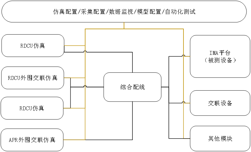
The basic principle of the IMA platform integrated environment is to achieve efficient verification and integration of avionics systems through a comprehensive simulation and testing framework. The system is based on modular design, combining simulation configuration, data acquisition, monitoring and model configuration to ensure that the system can operate stably in different operating environments. Through comprehensive wiring, modules such as RDCU simulation and peripheral cross-linking simulation are connected to the IMA platform to achieve seamless switching between simulation and real parts. This architecture not only supports real-time data exchange and monitoring of complex systems, but also provides automated testing capabilities, making the testing process more efficient and consistent.
When designing the architecture of a comprehensive verification environment, the hardware is divided into five levels according to the hierarchical structure. The functional positioning of these five levels is as follows:
a)Control and display layer:
● Integrated Environmental Control and Operations Center
● Test bench test operation monitoring display layer
● Test bench mechanism display, health status monitoring display layer
b)The computing resource layer mainly provides computing resources, including:
● Simulation Server
● Virtual bus computing node
● Clock Server and NAS Storage Server
c)The signal resource layer provides the connection of the simulated resources of the device on the receiving side, including:
● Signal resources include: ARINC664, ARINC429, ARINC825, ARINC818, RS422, analog quantity, discrete quantity;
● 28V and 115V power supplies;
● Provide signal simulation, stimulation and acquisition;
d)Testbench interface layer, including:
● UUT Connectors;
● Wiring and switching resources;
e)The connection resources of the device/system under test, mainly including connection cables and UUT racks:
● The device under test is placed on the ARINC600 bracket
● The bracket is installed on the EE BAY stand
● A standard ARINC600 aviation plug is used between the device under test and the ARINC600 bracket.
● The test bench signal interface cabinet and the ARINC600 bracket are connected via a transfer cable
● The test bench end of the adapter cable uses a unified ZIF plug
● The ARINC600 bracket end of the adapter cable adopts aviation plug.
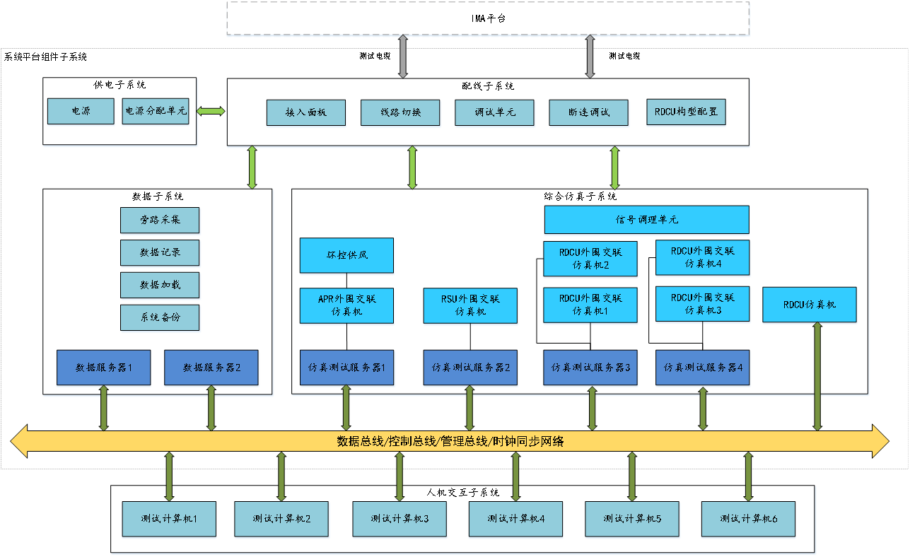
IMA platform comprehensive verification environment system architecture diagram

Contact: Bay Max
Phone: 136218783885
E-mail: max@novatech-js.com
Address: Science and Technology Innovation Park, Taicang Zhihui Valley, Suzhou City, Jiangsu Province
WeChat Public Number
©2024 Jiangsu NOVATECH Automation Technology Co., Ltd Powered by www.300.cn SEO Privacy Policy
Online Message